Slicer for 3D Printing
Part 1
- Task 1 - Create A Basic Slicer for 3D Printing
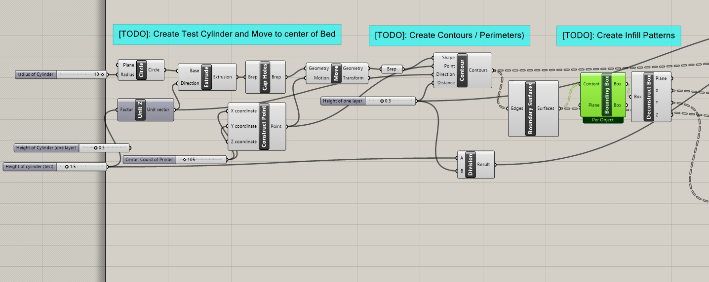
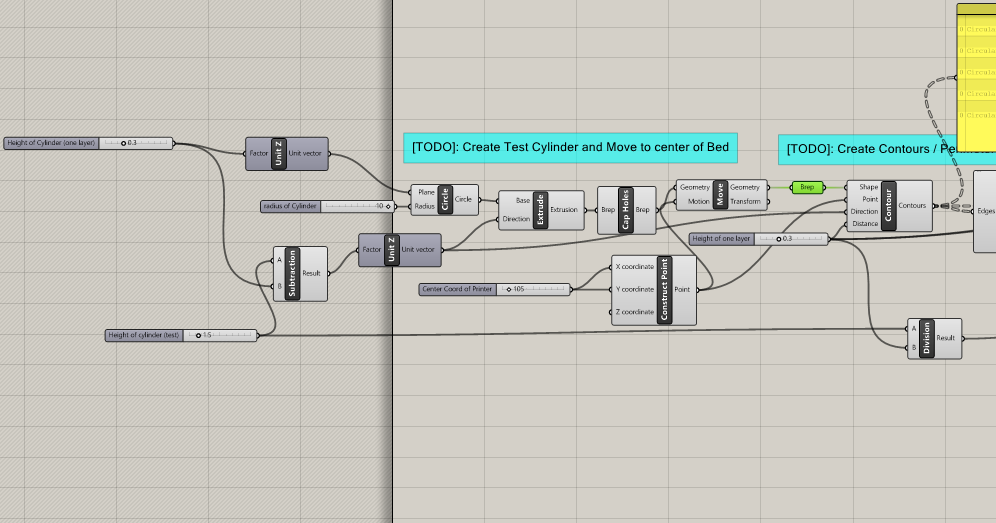
The goal of this task was to use Grasshopper to generate the curves a given 3D printer would have to follow in order to print an object. For simplicity's sake, the infill is calculated at 100%. Starting at one layer deep, the proper curves and lines for a cylinder are created.
I coded up the proper cylinder in its right place, then began the process of generating the data tree lists for layer division and bounding boxes.
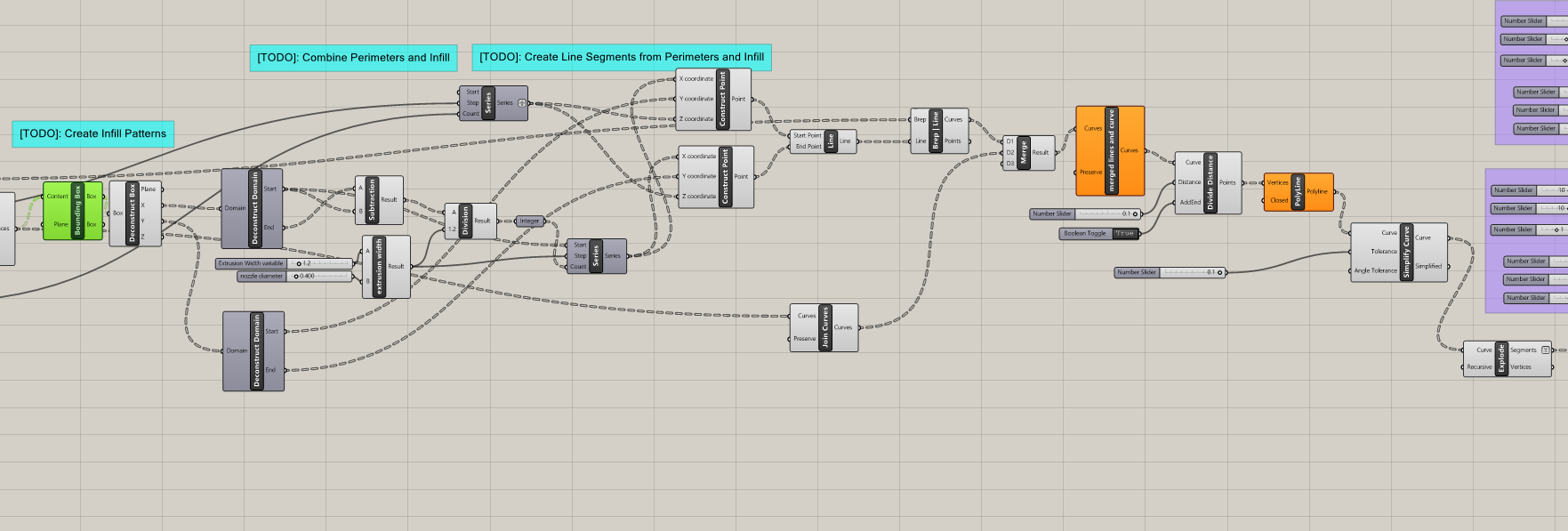
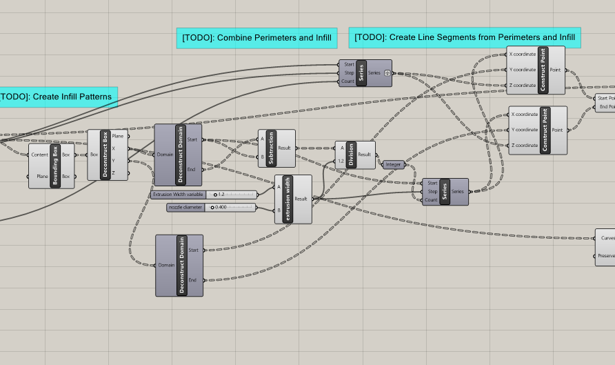
Next came the most difficult aspect of the entire project, the infill logic. in the Y direction, on either side of the bounding boxes, a carefully spaced out set of lines is drawn according to the provided machine specifications. Next, lines are drawn between these points, creating the familiar rectilinear pattern of standard infill. Eventually, a BREP Line component is able to trim the lines to within the curve that represents the perimeter of the cylinder/ object. Lastly, the lines are divided and simplified to be more suitable for workshopping in task 2.
Code:
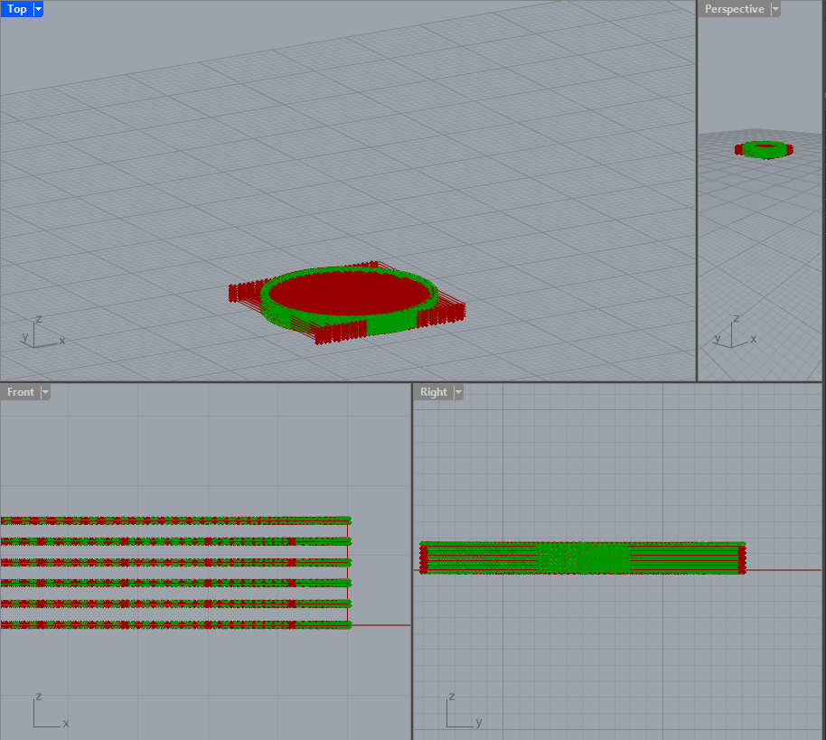
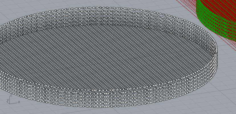
Output:
- Task 2 - G-Code Generator in Python/GH
Once the path was done, it was time to work in python to turn the Grasshopper elements and machine invariants into real g-code. I followed along through the Python file an completed all of the the TODOs.
I followed along through the Python file and completed all of the the TODOs
Python Code
Show Code
"""
This file contains parameters, helpers, and setup to
create a basic gcode generation algorithm from line segments.
The main
Inputs:
lines: the line segments to be converted into gcode commands for extrusion
nozzle_diameter: the diameter of the 3D printer's nozzle
filament_diameter: the diameter of the 3d printing filament
layer_height: the height of each layer in the print
extrusion_width: the width of the extruded line from the printer
travel_feed_rate: the speed at which the extruder moves in X and Y
layer_change_feed_rate: the speed at which teh extruder moves when
changing layers in the Z direction
extrusion_feed_rate: the speed at which the extruder move when extruding
Output:
gcode_output: a string with gcode commands separate by new-lines"""
__author__ = "mrivera-cu"
import rhinoscriptsyntax as rs
import math
########## CONSTANTS BELOW ###############
# GCODE COMMANDS
COMMAND_MOVE = "G1"
# GCODE PARAM NAMES
PARAM_X = "X"
PARAM_Y = "Y"
PARAM_Z = "Z"
PARAM_E = "E"
PARAM_F = "F"
# Separates commands
COMMAND_DELIMITER = "\n"
# Precision for converting floats to strings
E_VALUE_PRECISION = 5
XYZ_VALUE_PRECISION = 3
# Float equality precision
FLOAT_EQUALITY_PRECISION = 5
# Converts a float (f) to a string with some precision of decimal places
# For example:
# Input: f=0.1234, precision=3
# Output: "0.123"
def float_to_string(f, precision=XYZ_VALUE_PRECISION):
f = float(f)
str_format = "{value:." + str(precision) +"f}"
return str_format.format(value=f)
# Helper to convert the E value to the proper precision
def e_value_to_string(e):
return float_to_string(e, E_VALUE_PRECISION)
# Helper to convert the XYZ value to the proper precision
def xyz_value_to_string(e):
return float_to_string(e, XYZ_VALUE_PRECISION)
#########################################################################
# Helper function to compare floats in grasshopper/python due to float precision errors
def are_floats_equal(f1, f2, epsilon=10**(-FLOAT_EQUALITY_PRECISION)):
f1 *= 10**FLOAT_EQUALITY_PRECISION
f2 *= 10**FLOAT_EQUALITY_PRECISION
return math.fabs(f2 - f1) <= epsilon
# Helper function to compare if two points are equal (have the same coordinates)
# by handling float precision comparisons
def is_same_pt(ptA, ptB):
return are_floats_equal(ptA[0], ptB[0]) and are_floats_equal(ptA[1], ptB[1]) and are_floats_equal(ptA[2], ptB[2])
########################################################################
# creates a string consisting of a G1 move command and
# any associated parameters
def gcode_move(current_pos, next_pos, feed_rate=None, should_extrude=False):
# Start with "G1" as command
move_command_str = COMMAND_MOVE
# Compare X positions
if not are_floats_equal(current_pos[0], next_pos[0]):
x_value = float_to_string(next_pos[0], precision=XYZ_VALUE_PRECISION)
move_command_str += " " + PARAM_X + x_value
# Compare Y positions
if not are_floats_equal(current_pos[1], next_pos[1]):
y_value = float_to_string(next_pos[1], precision=XYZ_VALUE_PRECISION)
move_command_str += " " + PARAM_Y + y_value
# Compare Z positions
if not are_floats_equal(current_pos[2], next_pos[2]):
z_value = float_to_string(next_pos[2], precision=XYZ_VALUE_PRECISION)
move_command_str += " " + PARAM_Z + z_value
if should_extrude:
dx = next_pos[0] - current_pos[0]
dy = next_pos[1] - current_pos[1]
dz = next_pos[2] - current_pos[2]
distance = math.sqrt(dx**2 + dy**2 + dz**2)
# Updated capsule model:
# Use the corrected rectangle area: layer_height * (extrusion_width - layer_height)
rect_area = layer_height * (extrusion_width - layer_height)
semi_circles_area = 0.25 * math.pi * (layer_height ** 2)
v_out = distance * (rect_area + semi_circles_area)
# Filament volume = π * (filament_diameter/2)^2
filament_radius = filament_diameter / 2
filament_area = math.pi * (filament_radius ** 2)
e_value = v_out / filament_area
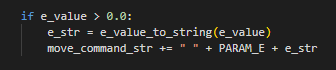
if e_value > 0.0 and e_value < 5:
e_str = e_value_to_string(e_value)
move_command_str += " " + PARAM_E + e_str
if feed_rate is not None:
feed_rate_value = round(feed_rate)
move_command_str += " " + PARAM_F + str(feed_rate_value)
move_command_str = move_command_str.strip(" ")
return move_command_str
############################################
############################################
############################################
''' Here's the main method of the script that uses the helper methods above '''
def generate_gcode():
current_position = [0, 0, 0] # start extruder at the origin
all_move_commands = [] # list to hold for all the move commands
for i in range(0, len(lines)):
line = lines[i]
start = line.From
end = line.To
start_pos = [start.X, start.Y, start.Z]
end_pos = [end.X, end.Y, end.Z]
# Step 1: Z change (layer change)
if not are_floats_equal(current_position[2], start_pos[2]):
z_only_pos = [current_position[0], current_position[1], start_pos[2]]
layer_move_cmd = gcode_move(current_position, z_only_pos, feed_rate=layer_change_feed_rate)
all_move_commands.append(layer_move_cmd)
current_position = z_only_pos
# Step 2: Travel move to start of segment if necessary
if not is_same_pt(current_position, start_pos):
travel_cmd = gcode_move(current_position, start_pos, feed_rate=travel_feed_rate)
all_move_commands.append(travel_cmd)
current_position = start_pos
# Step 3: Extrude along the segment
extrude_cmd = gcode_move(current_position, end_pos, feed_rate=extrusion_feed_rate, should_extrude=True)
all_move_commands.append(extrude_cmd)
current_position = end_pos
# Step 4: Combine with start and end gcode
gcode_lines = start_gcode_lines + all_move_commands + end_gcode_lines
# Final output
output = COMMAND_DELIMITER.join(gcode_lines)
return output
''' RUN THE MAIN FUNCITON ABOVE - DO NOT EDIT '''
# this sets the gcode commands to be the the `gcode_output` variable of this grasshopper component
gcode_output = generate_gcode()
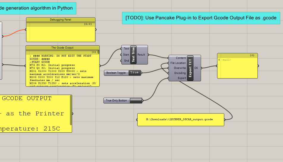
- Task 3 - Exporting and Validating Generated G-Code
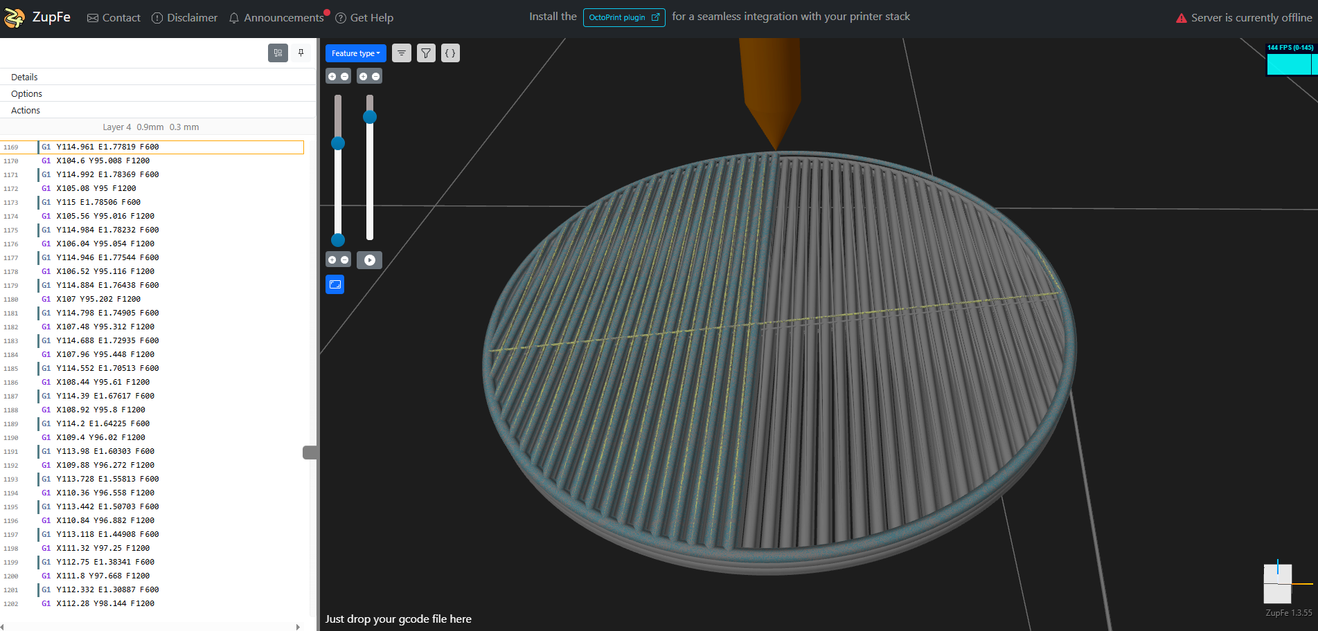
Using the pancake library, a simple setup can be assembled to export and test the generated g-code. Which is then tested first through a web-based g-code visualizer called Zupfe, and then finally through a dedicated g-code tester.
Pancake Export TXT:
Zupfe:
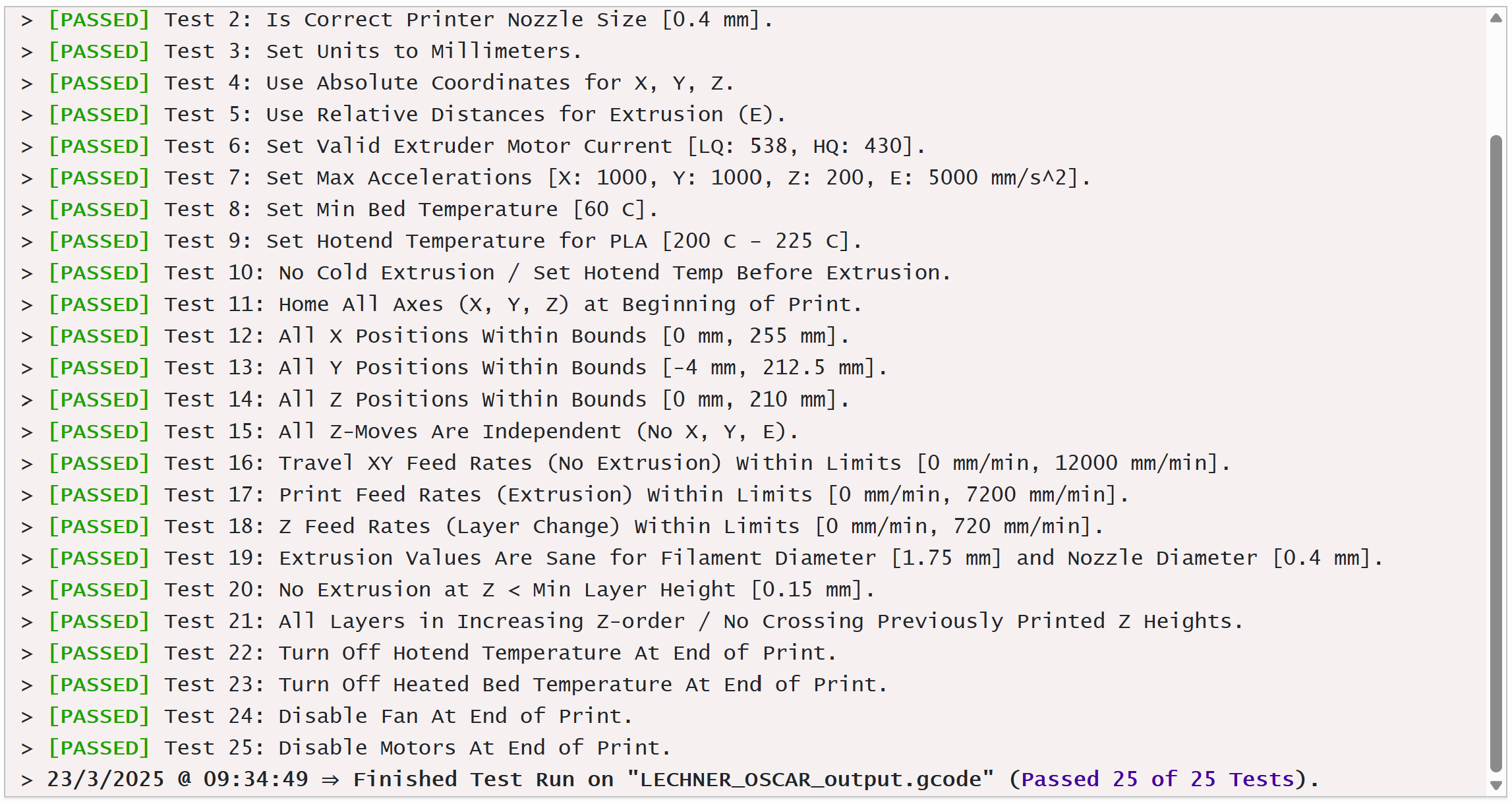
Prusa MK3S+ G-CODE Validator:
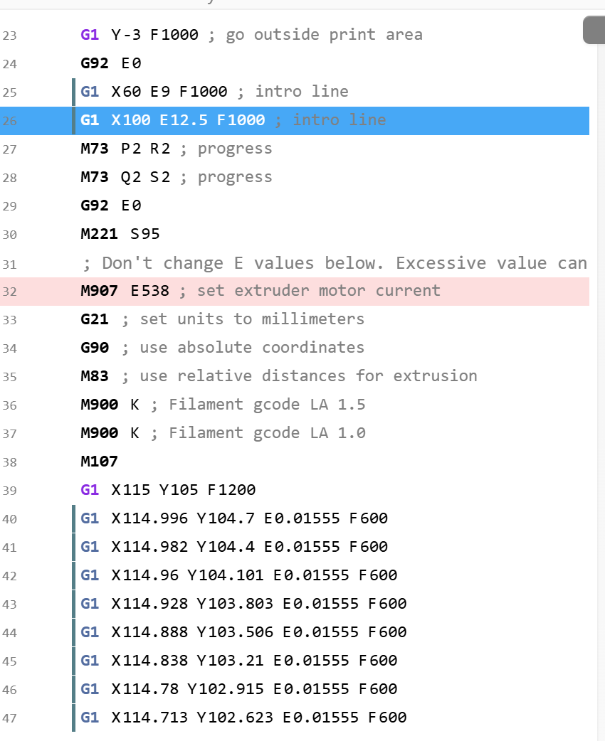
Example Screenshot of g-code Output:
My Files:
Part 2: Printing Output and Comparing
Since my g-code successfully passed the printer-specific validator as seen above, there were very few tweaks that needed to be made before I was finally ready to
bring my efforts to the BTU and print it out.
Firstly, I rerouted some key values in the beginning portion of my Grasshopper code to avoid creating and extruding along a contour at
Z = 0. I accomplished this by moving the simulated object up one layer height while also subtracting the z-height by that same layer height. This is admittedly not the most robust
work-around, however it worked wonders and I never had to weasle my way through the delicate mess that is my data tree.
Secondly, the series component I was using directly
before my "construct point" components had a terrible set of value being injected into it so I pulled some more correct and adaptable value from the earlier stages of the code such that the
infill line met up nicely and merged properly with the new contours. Finally, in my python, I removed a silly hard-coded infill volume upper-limit restricion that served no purpose other than
to remove a point from my grade on part 1.
With these finishing touches I made my way to the famed MK3s+ that resided in the BTU and printed.
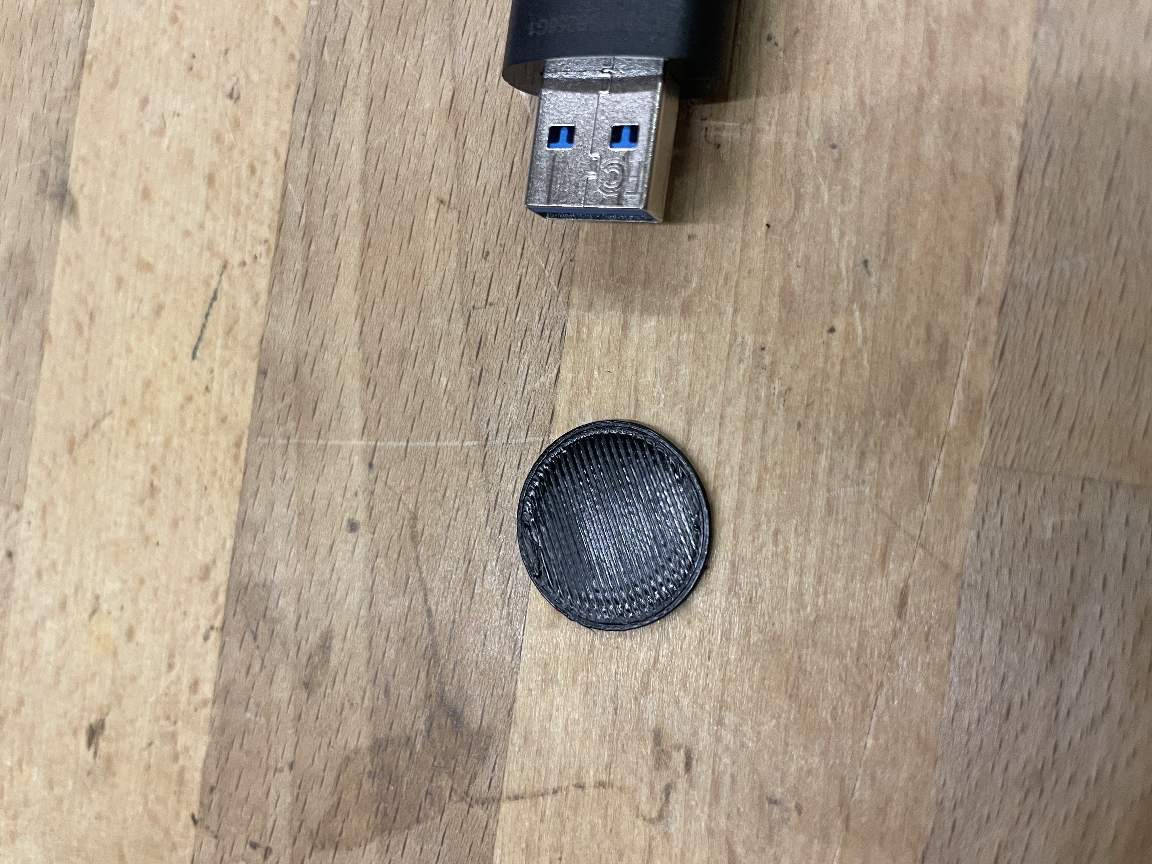
Printed Output
Prusa Slicer Constant - Top Down View
Front View
Prusa Slicer Constant - Side View
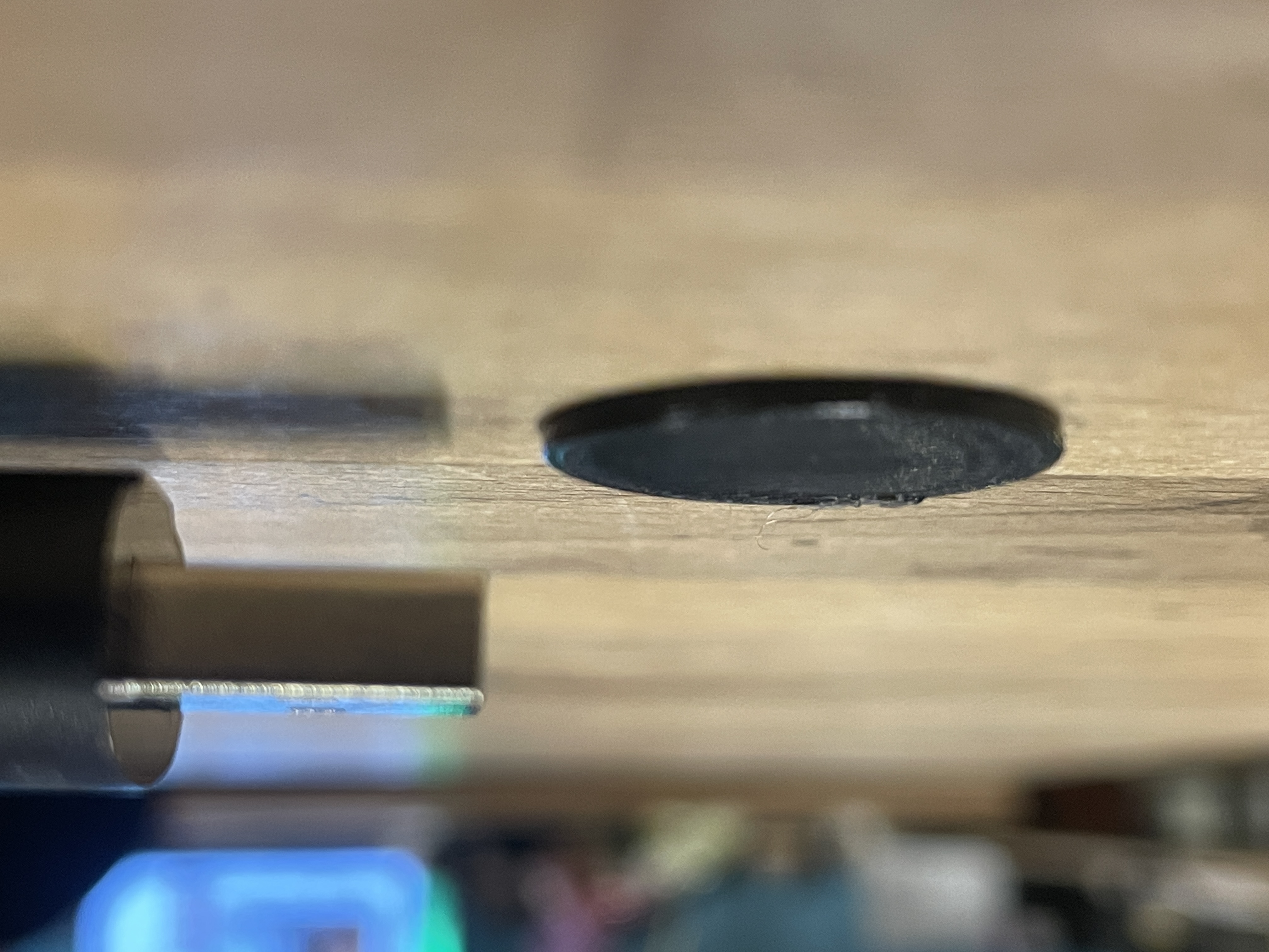
Side View
My G-CODE - Top Down View

Top View
My G-CODE - Side View
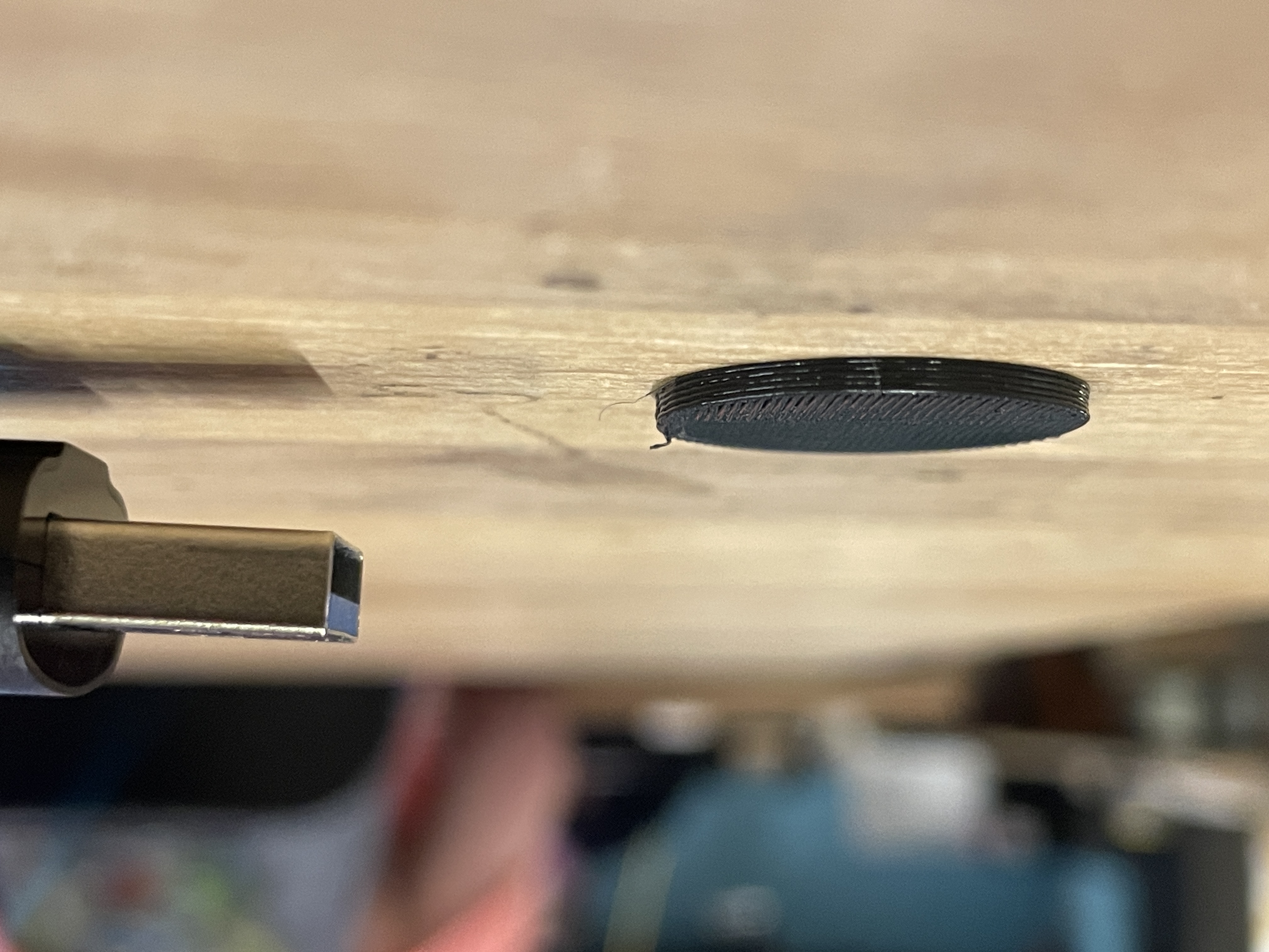
Bottom View
Prusa (left) and mine (right) - Top Down View
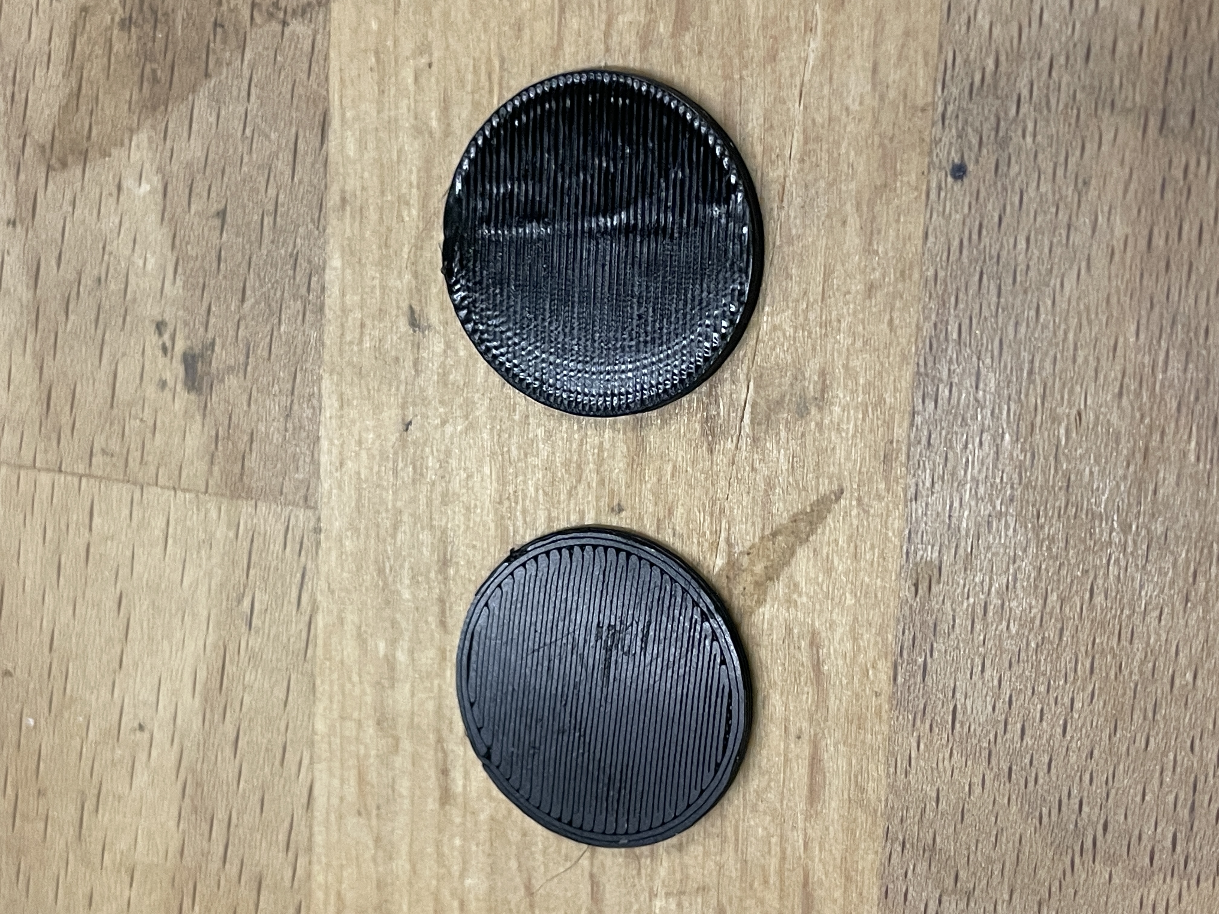
Angle 1
Prusa (left) and mine (right) - Side View
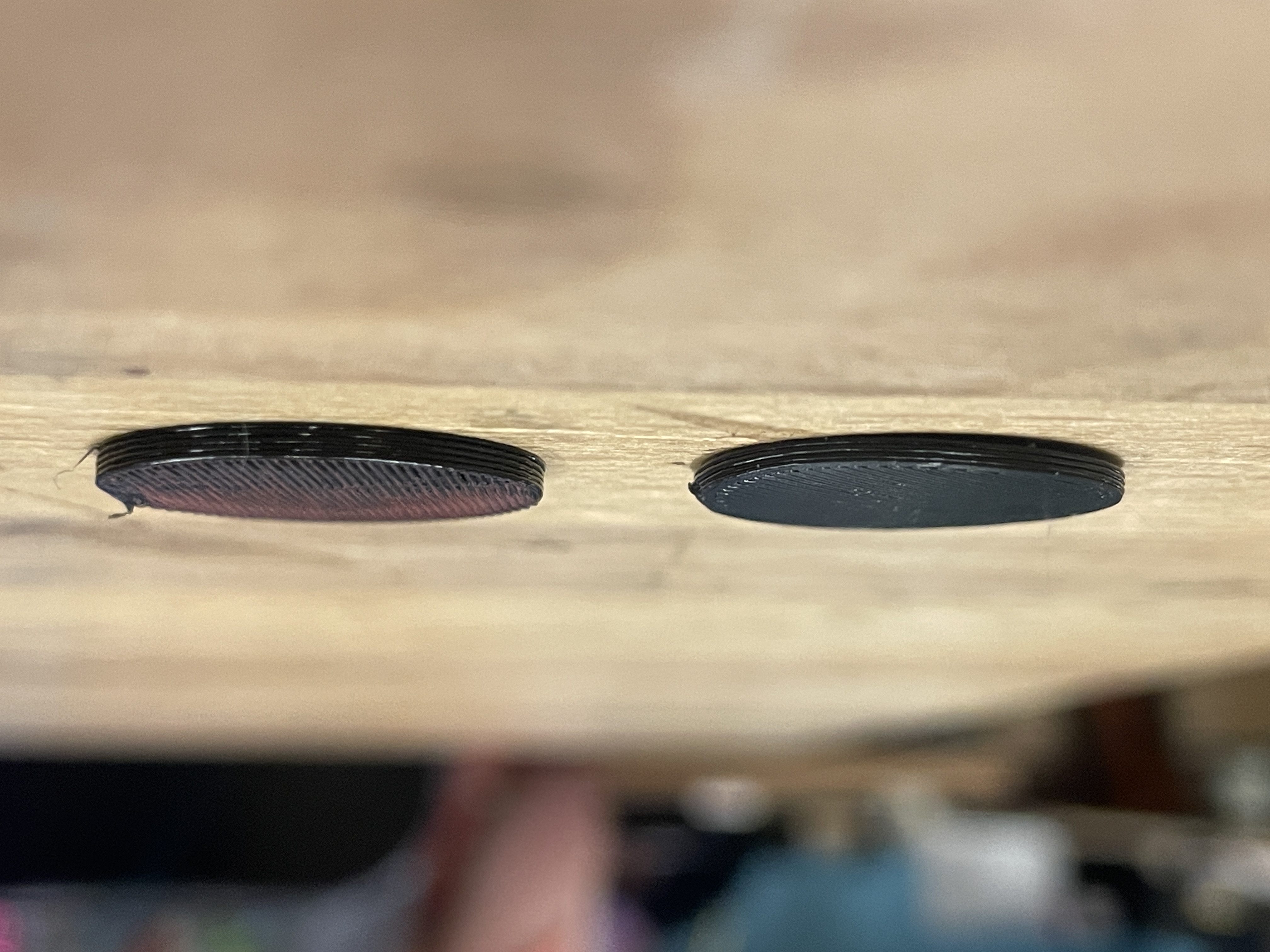
Angle 2
My printed output, although surprisingly good, is noticeably of worse quality than the Prusa-sliced version. The lines are less clean, the finish is bumpier, and there is a weird void space on one side. However, I can say that it worked first try.
My FINAL Files:
Conclusion
In conclusion, this project was a lesson on Grasshopper data tree mechanics, and a fundamentals crash-course on extrusion math and 3d printing logic/ processes. I learned a ton about these subjects and more, and I'm excited to bring these skills forward with me in my final project and beyond. Grasshopper is significantly more powerful than I initially believed, and just by tying together a few nodes, very cool things are possible. My greatest challenge in this assignment was debugging my components such that the data tree was kept consistent throughout, but after overcoming this challenge, I feel more confident with the tool and more ready to tackle bigger things. If I were to do this project again, I would be faster and more clean with my Grasshopper, and might have even tried to apply my system to a more complex object.